A complex helix for visualising a pedagogic hypothesis
in
3D Modeling Design
held by
mjl2009
Last seen:
Contest Ended, Winner(s) have been selected.
-
Open
-
Choosing Finalist
-
Ended
Description:
The spiral of learning (Kolb & Kolb) is a simple helix visualising the learner's progress. I need to visualise a more complex spiral. Turns on this helix are circular. Each turn represents an interaction between teacher and learner. This helix contains 1 grand turn. A grand turn contains at least 3 smaller turns. This creates a turn complex. Each turn achieves a small or large rise on the z axis depending on the diameter of the turns on the x and y axes. In elevation view the turn complex should have a stepped appearance due to the presence of the smaller turns, with the lowest steps at left and the highest at right. The idea to be communicated is that the larger turns contain at least 3-5 smaller turns. Each turn achieves a small increase in z-height as the learner exits the turn, like freeway traffic using a cloverleaf junction. Multiple interactive turns aggregate to a large gain in z-height. In the attached illustration, the largest loop should be understood as not a part of the visualisation. I would like to see two variations of the design:(1) smaller turns ranged on outside of grand turn diameter
(2) smaller turns ranged on inside of grand turn diameter.
Wants:
The structure is of 'sheet metal' form with a minimal sheet thickness and ribbon-like form factor. Blue semi-transparent material is preferred to reflective metallic material, so that overlaps and crossings are salient. It can be manipulated in 3-space using display software, or at least displayed as an animation of prerecorded rotations, eg, from plan to elevation view and back to plan view. The model can be output in different orientations and magnifications as a 300 dpi PNG or JPG illustration.
Don't Wants:
3D printing, machining or physical production. This is a virtual object for the visual representation of a pedagogic concept. It does not have to conform to any engineering or manufacturing standards.
Software:
- SolidWorks
- AutoCAD
- PTC Creo Parametric
 Prepaid Prize
Entries


#11 Spiral path - By Adriano Ordoz Barissa
by Adriano Ordoz Barissa

Download Files
Dec 14, 2016 16:08
Discussion
Thank you to all designers who made submissions. Designers of entries Number 11 and Number 10 
 as well as Peter Lakatos clearly had the technical skills to win, but in this case the quickest designer to resolve the design brief to all specifications was Handsketcher.
as well as Peter Lakatos clearly had the technical skills to win, but in this case the quickest designer to resolve the design brief to all specifications was Handsketcher. 
Hello please see the message i sent you.
Thanks!
Thanks!

Hi mjl2009,
I have sent a message yesterday. Please can you check it.
I have sent a message yesterday. Please can you check it.

I've now seen from some sketching of my own that the variant I describe in the project brief as "(2) smaller turns ranged on inside of grand turn diameter " is not going to work. This variation is therefore not required. As far as I can see, no designer has done this anyway. My apologies if you were preparing that variant.
Hello designers. I added a concept drawing using submitted artwork to show one treatment of the free ends that I want to use, implying fractal or self-similar relationships between all the helical turns.
So far Handsketcher's design, Number 5, has come closest to what the helix should look like. The pdf-readable animation is also the best suited to my needs for the live 3D rotations I would do when discussing the model with an audience.
This project is now pre-paid.
Hi JL, please note that the project is *not* for 3D printing, but graphic display only. I only need a visualisation of your design capable of being viewed as a video animation at 720p, and captured as still images from different viewpoints in 300 dpi PNG or JPG format. I will also need to show my audience images of details from the structure, such as a single minor turn.
The minor turns in my concept drawing are 33% the diameter of the grand turn. I am happy with the appearance of the structure at that ratio of minor turns to grand turn. Please note how 'flat' the structure is in the z axis; the gradient of the rise is quite shallow. Entry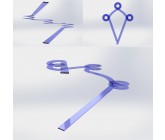 has an excessive rise over run. The gradient must be consistent through all turns. I would also like to see variations: minor turns on the inside of the grand turn; and on the outside as drawn in the concept drawing; and 3, 5 or 6 minor turns.
The minor turns in my concept drawing are 33% the diameter of the grand turn. I am happy with the appearance of the structure at that ratio of minor turns to grand turn. Please note how 'flat' the structure is in the z axis; the gradient of the rise is quite shallow. Entry
has an excessive rise over run. The gradient must be consistent through all turns. I would also like to see variations: minor turns on the inside of the grand turn; and on the outside as drawn in the concept drawing; and 3, 5 or 6 minor turns. 
Hi mjl2009, for the turns do you have any specific radius? The grand turn and the smaller turns. From your description and wants section of the contest you have not specified how large you would like this to be 3D printed. I have made a design that I believe you will like, the grand turn is 15cm and the smaller turns are 7cm, making this a hand held model. However this can be changed to anything you desire. Please let us know if you would like this to be sized according to holding the model with 1 hand, holding it with both hands (approx 30cm grand turn) or a larger scale.
I will do my best to make this exactly what you would like, I will upload my designs in a few days to give you time to reply to my question about the general size of the coil 3D model
I will do my best to make this exactly what you would like, I will upload my designs in a few days to give you time to reply to my question about the general size of the coil 3D model
I updated the attached concept drawing to give a better sense of what is required. The sentence in the project description about 'the attached illustration' now no longer applies.
Some further specifications that may help:
-semi-transparent blue glass material
-white background
-no drop-shadow
-semi-transparent blue glass material
-white background
-no drop-shadow
Similar Contests on Cad Crowd
Liver Shell
Design should be of a liver shell. It should be an anatomically accurate model that can be printed if needed to. The inside should be hallow and the liver should include a hole on top where the hyper-vein would normally be and a hole on bottom where the vein would leave. The liver shell should be a 2 piece design that can be clicked/ screwed together to symmetrically put together the 2 halves.
http://www.exchange3d.com/3D-Model-of-Liver-Anatomy/prod_28235.html#preview
A more simplified version of this will be perfect.
KC Royals 3D Printed Trophy Competition
Winning design wins $1500 in cash and website credit!
We’re now accepting submissions and have extended the submission deadline to give everyone Turkey Day weekend as extra time to perfect their design (or to submit multiple designs!). Please send us your submission(s) before end of day Monday, November 30th, by emailing trophycontest@3Diligent.com with the following details:
Your trophy CAD file
Your name, birth date, address, telephone number and preferred email address
Your preferred printing process for the design
Your preferred materials and finish for the design
Here’s a link to the official contest rules: http://news.3diligent.com/trophy-contest-terms/
J-shape
3D modeling of a J-shaped massage tool, much like a Theracane only smaller in dimensions. The tool should be modeled as close as possible to the attached images. The straight portion of the J-shape is approximately 10 inches long and 3/8in in diameter. The hook portion of the tool should form an approximately 180 degree arc and terminate in spherical end of 9/16in diameter. The handle, at the top of the J-shape, should be approximately 3/4in in diameter. The attached jpg images are of the actual tool that I would like modeled and should give you a good idea of it's dimensions. The png file should also provide a good reference. Thanks.
furniture
wood working projects
redraw from maya to solidworks
the job is to REDRAW NOT CONVERT maya file to solidworks
i don't want surface modeling , i want normal bodies in solidworks , don't convert the file , i want to redraw it totally in the solidworks
mjl2009
Buyer