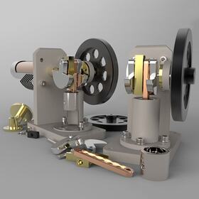
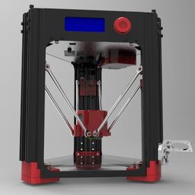
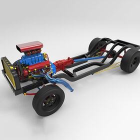
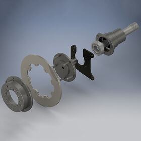
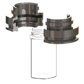


Businesses across the globe are increasingly turning to 3D assembly modeling as part of their product design cycle. It is an excellent way to save time and reduce errors in manufacturing products. The freelance experts at Cad Crowd have the experience to create 3D assembly drawings for your project, whatever your needs.
We can start with the 3D models you have created yourself or use our 3D modeling design services to develop accurate, highly detailed assembly models. The benefits of using assembly models will be discussed in a bit, but it would help to understand these models better if we first discuss 3D models in general.
Surface modeling (sometimes referred to as facet modeling) generates an image depicting a solid object's outside surface. While an object may have internal parts, its surface model contains limited information, and even then, information only about the exterior shape. There are two crucial distinctions between a surface model and a solid model (solid modeling will be discussed in just a moment):
The first distinction is that a surface model only approximates the shape of the object's exterior. This has advantages and disadvantages. One of the advantages is that the image can be initially constructed and eventually displayed much more quickly than a solid model using far less of a computer’s processing power. One of the disadvantages is that the dimensions of the object being modeled are stored in memory only as an approximation to the actual measurements. This can have serious repercussions when it comes to joining the internal components since the tolerances of those measurements are often critical to the performance and safety of the product.
Thanks to improvements in computer processing power and the increasing sophistication of Computer-Aided Design (CAD) software, the model's surface can approximate a much finer level of detail. Surface modeling software accomplishes this by creating tens or even hundreds of thousands of tiny polygons to approximate the shape of the model's exterior. While the level of detail can be so satisfactory that curved surfaces can visually appear smoothly to the naked eye, it is essential to remember that each of these polygons is flat. Regardless of how smooth the surface model appears to a viewer, the surface itself is just a mathematical approximation of its actual shape.
As mentioned above, the second distinction is that a surface model contains no information about the object's interior. No data is stored about whether any individual point is in the interior, on the surface, or outside of the model in the image. With the right software, you can rotate the object to look at it from any angle, and some programs even contain an “x-ray” viewing feature that treats each of those surface polygons like a piece of glass, allowing you to look inside the model. (But, since a surface model contains no information about its interior, there would be nothing to look at.)
Solid modeling (sometimes referred to as b-rep modeling, short for boundary representation) is sculpting a 3D computer image of the entire object. Both the surface and the interior are depicted. To describe solid modeling more thoroughly, let’s revisit the two distinctions outlined above:
A surface model is only an approximation of the object's shape, but the CAD software describes a solid model exactly. The object is precisely modeled mathematically in exacting detail. As a result, solid modeling is much more computationally intensive and requires more computer memory than surface modeling.
A surface model contains no information about the object's interior, but the position of every point in a solid model is known. This information allows us to view anything inside or outside of the model.
It’s worth noting that surface and solid models can look the same. A surface model can be rendered to make it appear more solid and realistic. But even though it would look solid, it would still be just a surface model; it wouldn’t be as accurate as a solid model and wouldn’t contain the same amount of detailed information.
Instead of being a solid metal or a hollow shell, what if a solid model was designed to contain information about all the internal parts? The exact size and position of every single component could be displayed. It would look like an assembly of all the parts of the model. Hence the name—assembly model.

Assembly modeling is creating, typically through CAD software, a 3D solid product model that includes all of its parts. These components often move (slide or rotate) in relation to each other, and a part may be composed of other components.
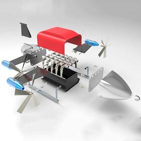
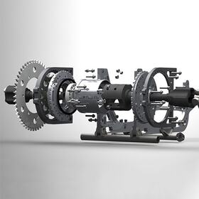
The idea of drawings and models that display component information has been around for a long time. Precursors of assembly drawings are illustrations known as exploded views or exploded drawings—images that show the components of an assembly in a slightly separated fashion but drawn in such a way that they clearly show the relationship of the parts to each other and the assembly as a whole.
Exploded drawings can be incredibly complex and detailed but are often used for simpler designs, such as the bar-yoke assembly. But as you can imagine, if you tried to depict a jet engine and its components as an exploded drawing, it could quickly become so large and complicated that it would be difficult to comprehend or use effectively.
That’s one of the reasons designers often prefer to use assembly modeling instead. Digital assembly drawings can be manipulated to better display the relationship of the individual components to each other.
Generally, two assembly modeling processes are recognized—top-down design and bottom-up design. These two hybrids exist, but most businesses choose one or the other of these processes, depending on the individual project.
In top-down designs, the starting point is the big-picture view of the overall product. Once the project's overarching design is firmly established, the assembly model can lay out the specifications of the components that need to be produced. Top-down design is beneficial when the desired attributes of the finished product are known in advance. Individual, customized components, like chains and brackets, can then be designed to ensure the final assembled product will perform as expected.
In bottom-up designs, the components are designed first. They are created to perform desired functions within specific parameters and are designed to work with each other. After the components have been brought together in the assembly model, problems can be identified and corrected. Bottom-up design is efficient if the assembly will contain off-the-shelf components, like original equipment manufacturer (OEM), or aftermarket parts, such as pulleys and belts. The assembly model can be designed and modified to accommodate the dimensions of these existing components.
Whatever your design methodology, accurate solid assembly models drawn and updated efficiently and promptly are critical. Cad Crowd’s extensive network of professionals can help you find a professional willing to work with your company’s internal processes to provide precisely what you need when you need it.
People all around the world engaged in businesses of all sizes make use of 3D assembly modeling services:
| Component manufacturers | Entrepreneurs |
| Consumer-goods manufacturers | Industries of all types |
| Consumers | Inventors |
| Designers | Parts suppliers |
| Engineers | Prototype builders |
3D assembly modeling during product lifecycle management has become mandatory for most industries. And while there are necessary costs associated with implementing this, there are also enormous benefits to be realized. Benefits such as:
Using virtual tools to create assembly models during your project's design and implementation stages can save significant time. (See, for example, this study.) Time savings can also be realized because each component of an assembly is a distinct 3D model in its own right—several people can be working on a given assembly at the same time, with each person designing or modifying a different component, reducing the overall time needed to finish the overall model.
Through interference checks (often called interference analyses or interface checks), assembly modeling software can ensure that component specifications are accurate. This can result in a great potential for reducing errors that would translate into unusable parts or significantly degraded design performance.
Interference in an assembly can occur when one component bumps into (interferes with) another while executing its intended function (for example, a belt between two pulleys may rub against another component when the belt is in motion). An interference check will detect this during the design stage of your project. These interface checks can also be used to provide the following:
Because assembly drawings are built from solid 3D computer models, the dimensions and tolerances of all parts are stored in memory. Assembly models can use this information to ensure that component placement is accurate, resulting in greater assurance that the final product will perform as intended.
For example, a stock bracket may have been chosen to hold another component in place, but it might be too large to fit in its intended position. The CAD software could perform an interference check to bring this problem to light well before time and money were wasted during production. This naturally translates into:
The amount of information available to you when you utilize assembly modeling, coupled with best engineering practices, can help you ensure your products' quality. Assembly modeling software has been designed to help you optimize your product, even before time and money are spent to build a prototype. Some CAD software can even calculate suggested optimization solutions for you (PTC’s Creo Behavioral Modeling is an example).
Modern-day assembly modeling software will help you design better components. It will enable you to create those components to work well together. The better those components work together within your assembly, the higher the quality of the finished product.
Most CAD software programs allow users to generate a bill of materials (BOM). For the uninitiated, a BOM is just a list of the components that make up your assembled product. This list can contain quite a bit of information, though. BOM information available to those with 3D assembly drawings varies by software but can include information like part numbers, quantities, vendor names, and costs. The program updates BOMs automatically as changes are made to the assembly parts.
A 3D assembly model of a product makes it much easier to create variations or simplify your designs. With the right CAD software, you can easily and quickly modify or update assembly drawings as the criteria for the components or the assembly as a whole change.
As mentioned above, work on an assembly can be shared among several individuals simultaneously. Some CAD programs have taken this concept to new heights, with the system existing online in the cloud. There is no software to install on computers (although mobile devices may need a particular app installed for access). Users access the system through a web browser, anytime, anywhere in the world, with internet access. Project files are also stored in the cloud, which reduces the chances that multiple versions of those files might be stored on different computers.
Whether work is done online or across a company’s network, the collaboration made possible through multi-user access is vital to innovation and development in your product design. And perhaps the most crucial benefit of assembly modeling is:
As mentioned, some companies (Onshape is an example) have built assembly modeling capabilities in the cloud. Project files and associated intellectual property (IP) are stored securely and accessible only to designated users with approved log-in credentials. While it may be impossible to guarantee security regardless of the computer system, data storage in the cloud is much better than an arrangement where proprietary information is kept on a desktop or mobile device that could easily be stolen.
However, security for your IP, even outside the cloud, can still be very high. While some software packages (AutoCAD is an example) have security protocols like anti-virus countermeasures built in, the first line of defense within any organization will be a set of network best practices. These practices should cover security essentials such as (but not limited to):
With the proper safeguards in place, your assembly models and all the associated data can be secure, especially compared to the risks associated with storing and sharing paper drawings.
Most of the more powerful CAD software packages to design 3D models can also be used to create assembly drawings. Some of the more popular tools are:
| ANSYS SpaceClaim | Dassault SolidWorks |
| Autodesk AutoCAD | Siemens SolidEdge |
| Autodesk Inventor | SolidFace Technology's SolidFace |
| Dassault CATIA | SketchUp |
If you’re looking for an assembly modeling freelancer with specific software skills, please let us know when you request a quote.
Cad Crowd has the resources to help you achieve your project goals through 3D assembly modeling services. Professionally drawn, high-quality models will reduce the time and money you spend bringing your new products to market.
We can help you find the assembly modeling services company or freelancer to give you a leg up on your competition. Regardless of the complexity of your assembly models, Cad Crowd has the professional resources to help you manage your projects. Contact us today for a free quote.
No matter how complex your design project is, we’ve got professionals with the necessary skills and expertise to handle it. We can put you in touch with a 3D assembly modeling services firm that can deliver on your project quickly and accurately. We even back up this promise with our accuracy guarantee.
Our freelance assembly modeling designers are among the most talented in the industry. Cad Crowd has an extensive network of pre-qualified and vetted freelancers who can develop assembly models to help you complete your project on time and under budget. Contact us to obtain a free, no-obligation quote today!


