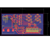
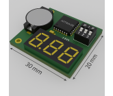
PCB for Mini LEDBlind
in
Electronic Devices
held by
gabrialw
Last seen:
Contest Ended, Winner(s) have been selected.
-
Open
-
Choosing Finalist
-
Ended
Description:
I'm looking for a CAD design for a concept I've come up with. My design is to create a small PCB with dimensions not exceeding (if possible) 20mm x 30mm x 6 mm. The small LED is powered by battery and is energized when a button is pressed. The LED connects to a DIP switch to show 1-99. A small button is depressed to turn on and display specific LED numbers. I'm not an engineer, if this design is not feasible let me know. I'm hoping it's straightforward.
Wants:
The following is the components to include in the CAD design:• PCB Size: ~30 mm x 20 mm (1.2 in x 0.8 in)
• Height/Thickness: ≤6 mm (0.24 in)
• Total Volume: ~30 mm x 20 mm x 6 mm (3.6 cm³), Component Selection for Compact Fit
1. Battery: CR1220 coin cell (12.5 mm diameter, 2 mm thick, 35 mAh, 3V).
o Use an SMD coin cell holder (~10 mm x 2.5 mm footprint, ~2.5 mm height).
2. Microcontroller: ATtiny20 (QFN-20).
o Size: 3 mm x 3 mm x 0.8 mm (vs. ATtiny85 SOIC: 5 mm x 4 mm).
o 12 I/O pins (sufficient for 7-bit DIP + button + LED).
o Low power, programmable via ISP.
3. LED: 0603 SMD LED (1.6 mm x 0.8 mm x 0.6 mm).
o Ultra-compact, available in various colors.
o Current-limiting resistor: 220Ω (0603, 1.6 mm x 0.8 mm).
4. Push Button: SMD tactile switch (3 mm x 3 mm x 1.5 mm).
o Low-profile, momentary switch for LED activation.
o Pull-up resistor: 10kΩ (0603).
5. DIP Switch: 6-bit ultra-miniature SMD DIP switch (e.g., C&K SDA06H0SBR).
o Size: ~8 mm x 3 mm x 1.5 mm.
o 6 bits cover 1–63; for 1–99, use a 7-bit switch (~9 mm x 3 mm x 1.5 mm, e.g., Omron A6S-7102-H).
o Each switch connects to a GPIO with a 10kΩ pull-up (0603).
6. Capacitor: 0.1µF decoupling capacitor (0603, 1.6 mm x 0.8 mm) for MCU stability.
7. PCB: Custom double-sided FR4 PCB, 0.8 mm thick.
o Dimensions: 30 mm x 20 mm x 0.8 mm.
o SMD components on both sides to optimize space.
o Thin PCB reduces total height.
The designer that meets the overall requirements will be the winner.
Don't Wants:
I need the designer to meet my specifications. If it's not possible, please let me know and I may be able to edit the requirements.
Additional Information
Please ensure the LED’s are two (.75 x .5 x .31 inch) side by side 7-segment LED’s. Please position on the upper right of the PCB and include an 8 position DIP switch. Lastly, I would like to give this design to a manufacturer to produce a sample. So, all of the resistors, capacitors, etc. need to be included in the design. I prefer a single side PCB please.
Entries
1st Winner
#9 Binary Switch to Digits
by khriss
#1 PCB 1.1
by ramins2
Download Files
#3 PCB 1.3
by ramins2
Download Files
#11 mini_led
by DebrajDas
Download Files
#13 Display LED
by rubertg
Download Files
Discussion
Thank you for clarifying. 70x35mm is still a pretty difficult constraint due to the shift registers required for the LED displays, and the size of the displays themselves, but I might be able to make it work.
actually, I originally meant 30x20 mm but I can make 35 mm x 70 mm if you can make that work
One final question before I submit my design. Is the 30x20mm dimension for the maximum board size what you intended? Or did you actually mean 3x2 inches?
Petert5 great question. In this cast the thickness of the led is ok. it will actually pop through a plastic cover. Hope that makes sense.
Should the overall height requirement be made thicker?
Or should the 7-segment LED height be made thinner?
Or should the 7-segment LED height be made thinner?
Your size specification for the 7-segment LED is the following:
0.750" H x 0.500" W x 0.310" D (19.05mm x 12.70mm x 7.87mm)
This doesn& ;t fit within the 6mm high requirement for the overall design.
Should the PCB be made thicker, or should the 7-segment LED be made thinner?
0.750" H x 0.500" W x 0.310" D (19.05mm x 12.70mm x 7.87mm)
This doesn&
 ;t fit within the 6mm high requirement for the overall design.
Should the PCB be made thicker, or should the 7-segment LED be made thinner?
Sorry for the confusion. I posted this under additional information: Please ensure the LED’s are two (.75 x .5 x .31 inch) side by side 7-segment LED’s. Please position on the upper right of the PCB and include an 8 position DIP switch.
Any other information about the board would also be appreciated, i.e. LED preferred colour, preferred position for the DIP switches, etc.
Hey, could you clarify what LED(s) you would like in the circuit? At one point you mention a single 0603 LED, but then mention 7-segment LEDs. Two 7-segment displays would have to be controlled a little differently than a single LED, If using 7-segment displays, that would possibly end up using another IC to handle the LEDs, some shift registers perhaps, or something along those lines. Is this acceptable?
Also, what would you like the dimensions of each LED segment to be?
Also, what would you like the dimensions of each LED segment to be?
I have been working in the construction sector for 11 years, developing strong skills in architectural design and construction management. During this time, I have designed and overseen the construction of two two-story villas, three single-story residential homes, and two five-story commercial buildings.
With my foundational design abilities, I can handle all aspects of architectural formation—both external and internal—and produce various design drawings for reinforced concrete, steel, and wooden structures. I am also proficient in structural design, from initial concepts to roof designs, complete with accurate calculations.
I am skilled in using several software programs, including BIM (Building Information Modeling), Revit, Robot, AutoCAD, ETABS, Advanced Steel, and 3Ds Max.
I take pride in my ability to create buildings that harmonize with the characteristics of the local environment, blending classical and modern styles. Additionally, I am passionate about designing green buildings that promote human health and well-being. I am eager to showcase my design skills by delivering your project in a contemporary and outstanding manner. I am confident that we can forge a lasting partnership.
I look forward to collaborating to achieve great goals for ourselves, our future generations, and our families.
Wishing you best!
Similar Contests on Cad Crowd
Electronic necklace device
Its an electronic device hanging by a chain from a neck.
2.5 x 2 x 1 cm is the size of electronic component inside of it, however we dont want it to be square. Those dimensions are given as rough estimate of total volume of device. It is water proof. 1 usb-c port on a side with a cover. And one sliding switch. And a place for a chain to go through.
Cellphone Charging Wallet
We created an idea for a cellphone case and would love help from a professional designer that specializes in cell phone cases. It is rather simple but we need help and expertise in this area as we lack the knowledge.
as of now, we just have drawings and need direction of steps on how to continue. Have a great day.
Redesign of a bluetooth headphone
We would like to launch a new generation of an existing headphone. We would keep the headband and critical structure exactly the same. I need a more modern version of a bluetooth headphone. Therefore structural design is not required. I need only a cosmetic design which is 70% same as the existing model but with a more high tech feeling. Length and Thickness could be slightly modified.
Ghost Hunting Equipment Mold Design
Greetings,
We are developing currently a device that will be used for Ghost Hunting Equipment.
The device will be a radio device, with specific features and functions which are intended to be utilized to be communicating with spirits.
We are looking to do a front and back mold/design appearance which will allow us to be unique and special on the marketplace.
You can find the current top 3 models in the market using the following link: https://www.amazon.com/s?k=Spirit+Box&ref=nb_sb_noss
Here they are:
1: https://www.amazon.com/Spirit-Ghost-Hunting-Equipment-Radio/dp/B00NABGFSM/ref=sr_1_7?dchild=1&keywords=Spirit+Box&qid=1628438922&sr=8-7
2: https://www.amazon.com/Spirit-Box-Temp-Built-Flashlight/dp/B08S5MPV52/ref=sr_1_3?dchild=1&keywords=Spirit+Box&qid=1628438922&sr=8-3
3: https://www.amazon.com/SBox-Ghost-Scanner-Spirit-Recorder/dp/B07KXZ5VL5/ref=sr_1_4?dchild=1&keywords=Spirit+Box&qid=1628438922&sr=8-4
We would want to aim to develop something different from all 3 models, yet, in the same time, keeping the functionality of a radio, as the mold will have to be around some form of radio device.
I am also attaching a few references for a few models
More information on the product:
A ghost box is a device used to verbally communicate with spirits. Many of these gadgets continually scan radio frequencies, creating a din of white noise. “The idea is the spirit can use that white noise to communicate in some way, either verbally or through EVP sessions,” Ober says. Users can simply listen for disembodied voices, or yell questions into the void and hope for an answer from beyond.
It is frequently used with other ghost haunting equipment such as cameras, flashlight, temperature meter, emf meter, voice recorder etc
You can use spirit box just to search for spirit voices or you can ask questions and wait for answers.
Mini-ITX Computer Case
Hi Everyone!
This contest is for the smallest Mini-ITX computer case with the following requirements:
-Includes rendering of a mini-itx motherboard
-Includes rendering of two nvidia 1080 video card in sli configuration
-Enough room for liquid cooling on cpu and video cards including radiator fan(internal or external).
-Includes rendering of 800watt SFX-L PSU
 Prepaid Prize


khriss
Designer