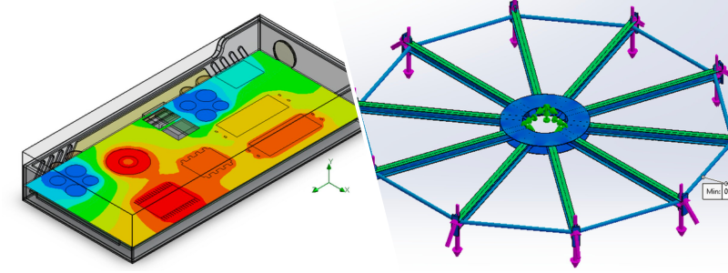
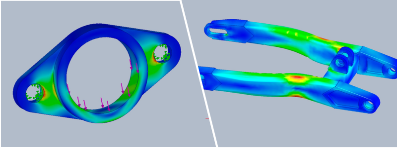
Finite element analysis (FEA) uses a computational mathematical method to subdivide a CAD model of complex geometrical and irregular shapes into individual elements for analytical simulation. A model or an object might comprise intricate and interconnected geometric figures. As a single entity, its structural behavior is as good as unknown. FEA breaks down the complex model into separate building blocks or geometrical elements —known as finite element method (FEM) mesh— so that engineers can isolate and gauge changes in the materials’ properties under impacted forces, such as heat and pressure. Once the analysis is done, FEA then reconstructs the model from those elements.
The term “finite” refers to the limited (as opposed to infinite) degree of changes allowed for each building block under load. It is a set of boundaries defined during a run of FEA analysis to govern the extent of permissible deformation on each building block. All materials have tolerance limits before they suffer from deformation. For example, aluminum alloy has an ultimate tensile strength of 241 – 300 MPa; an element of the material should not be exposed to stress beyond the range, or it will deform and cannot return to its original shape. If the object’s intended usage involves any load higher than the limits, it must use more substantial material.
An FEA simulation uses millions of elements that combine into the shape of the analyzed object. Each element is subjected to calculations, and their reconstruction process yields simulation results for the whole structure. In some regions of the geometrical mesh where the material behaviors cannot be determined, FEA software interpolates the calculation.
 Table of contents
How companies use FEA for products
Engineers and designers utilize freelance finite element analysis & FEA engineering services to simulate various physical phenomena on a computer screen. In practical use by the manufacturing industry, a digital product prototype in a CAD model is subjected to a series of virtual tests to see how its components react under given loads or conditions. Not only does FEA allow for science-based product optimization, but it also minimizes the necessity for physical prototypes in the design process. Although different companies have specific needs, most apply FEA similarly.
Meshing
The first step is always the same regardless of the product, structure, and material. FEA analysis starts with transforming a solid model into numerous geometric elements, represented by an overlay of 3D mesh on the model’s surface, hence meshing. Each element is a polygon and can be of any shape. All components are directly connected by the nodes, the points where the edges of polygons intersect.
In the old days, FEA meshing was done manually. The nodes were created mathematically, specifying their Cartesian coordinates to determine element connectivity. Manual meshing is a labor-intensive method. While engineers could theoretically exercise the method to analyze complex elements, the sheer laboriousness rendered the process practical only for simple structures like rods or shapes.
Modern FEA with automatic meshing is a giant leap from the traditional method. It can develop a mesh that contains millions of intricately shaped elements from even the most challenging structure in practically no time. The automation still requires manual input from users, but the process is much quicker and more accurate than the conventional way. Such an efficiency allows companies and engineers to perform FEA on models of products of all sorts.

The early 1990s saw the birth of various software tools (or healing programs) built explicitly for meshing. Most of the present-day automatic meshing functions can generate mesh on solid 3D and surface geometry CAD models from any source, as well as on two-dimensional sketches. The “healing” tools can fix potential geometrical inaccuracies, such as sliver polygons or gaps between the elements, and make the model airtight. Because the model will be eventually treated as a single entity, there can be no cracks on the mesh. FEA analysis will yield correct results. Many FEA software packages already incorporate healing tools into the mesh generator function.
RELATED: Finite Element Analysis costs, consulting company rates & engineering services pricing
Assembly analysis
The interaction between elements and components determines the analysis result of an assembly. When a single part of a product undergoes a deformation, the damage inevitably affects the assembly’s structural integrity. If the product has parts with a limited extent of permissible deformation, the overall design should allow the structure to absorb the impact and negate the effects.
A product’s structural integrity is defined by the materials’ strength and how the parts are assembled. Parts can be bolted, welded, or glued to form an assembly. Companies use FEA to figure out how the connections withstand external forces. The contact analysis function is a standard feature in nearly every FEA software in the market.
Structural analysis
Static or dynamic load is one of the most common external forces affecting a product. The structural analysis simulates a real-life situation when a volume of weight or pressure is applied to product parts or mechanisms. FEA software can determine how well the product retains the design and functionalities under load before it fails. The simulation-based analysis clearly shows what will happen to the product during excessive load.
Companies use structural analysis during the design phase to find possible flaws early on and subsequently improve product quality.
RELATED: What are CAE engineering costs, company consulting rates & services pricing?
Thermal analysis
As the name suggests, thermal analysis is all about heat or temperature. FEA simulation offers vivid imagery of how product parts and materials react to temperature loads. The analysis comes in two types:
- Transient: an analysis to determine the thermal quality of a model under varying temperatures. It is the most common form of thermal analysis used in most products.
- Steady-state: a simulation to calculate how a model reacts to constant thermal loads. The analysis is meant to determine heat flux and heat flow rates partly.
Thermal analysis is essential in consumer electronics, medical devices, automotive parts, and aeronautics products. However, it applies to products of any type.
Computational fluid dynamics (CFD)
FEA-based computational fluid dynamics uses mathematical calculation to visualize the flow of fluids. The simulation visualizes the behaviors of fluids when they interact with solids. Fluids are materials with zero rigidity, including liquid and gas. They cannot withstand tangential forces and will undergo continuous changes when exposed to stress. Since fluids are always affected by other objects and external loads, they may trigger heat transfer and increase the internal pressure of an enclosed system. A counterreaction follows every reaction.
Some of the most common applications of CFD include HVAC components, industrial piping and valve systems, combustion engines, aerodynamics, and electronics cooling design. CFD can help companies reduce production costs to a significant extent, thanks to the absence of physical prototypes and real-world experimentations.
RELATED: What are CFD engineering rates, consulting services costs & company pricing?
3D CAD interoperability
Several FEA tools come as stand-alone simulation software packages. Among the most popular include proprietary commercial software like SimScale, ANSYS, and Autodesk Simulation. Some are open-source and free, such as GOMA and FreeFEM.
Interoperability used to be a computational nightmare. Each time the model changes in CAD, the revised design must be imported to FEA software for every subsequent structural test session. All the test variables, like temperature, loads, and boundaries, will also need updating. The technicalities are massive, time-consuming procedures.

3D CAD models have replaced physical prototypes, whereas FEA simulation has supplanted real-world analysis. Using different tools for separate tasks is often a good thing. Still, the unavoidable interoperability between FEA and CAD favors an all-in-one functionality where both functions are available from a single software package. Many vendors now offer integrated suites like Dassault Systèmes SolidWorks, PTC Creo, Autodesk Inventor, and Siemens Solid Edge. Proper integration means the two functions operate simultaneously to update the models and restraints associated with every piece of geometry. When changes happen in CAD, the models are automatically revised in FEA, too.
The combined features of two powerful computational product modeling and element analysis come with the notion that 3D artists and designers, even without engineering backgrounds, should be able to dissect a virtual prototype down to the tiniest detail. More commonly referred to as the push-button solution, the approach allows companies to discover the most effective and workable design for every product development.
RELATED: How much does product design cost & what are prices for freelance design firms?
Approximation at best
Under each load type and condition, FEA can predict to what extent the product fails. The simulation demonstrates how a product, parts, components, or assemblies will work according to the design requirement and whether the structural form is appropriate for the normal intended usage. Some tests are meant to determine durability if under-utilized and overused.
Every vendor tries to create software packages to simulate real-world experimentation as accurately as possible. Despite relentless attempts and advances in computational powers, FEA results must be treated as mere approximations. FEA simulation results may resemble physical testing, but the former will not wholly replace the latter’s validity. Accuracy depends entirely on the user’s understanding of the modeled product’s material properties and structural behaviors. All modeling assumptions, limits, geometrical subdivisions, and external force characteristics are only as precise as the inputs by the users.
How Cad Crowd can help
Discover the essence of finite element analysis (FEA) and its pivotal role in product development and optimization. Recognize how leading companies harness the power of FEA to bring innovations to life, ensuring durability, efficiency, and excellence.
Venture into our insightful blog post to grasp the fundamentals of FEA, its applications, and its transformative impact on product design and testing. Are you eager to integrate FEA into your product development process? Contact Cad Crowd for expert insights and guidance, helping you to capitalize on the benefits of FEA seamlessly. Dive in and elevate your product game!
