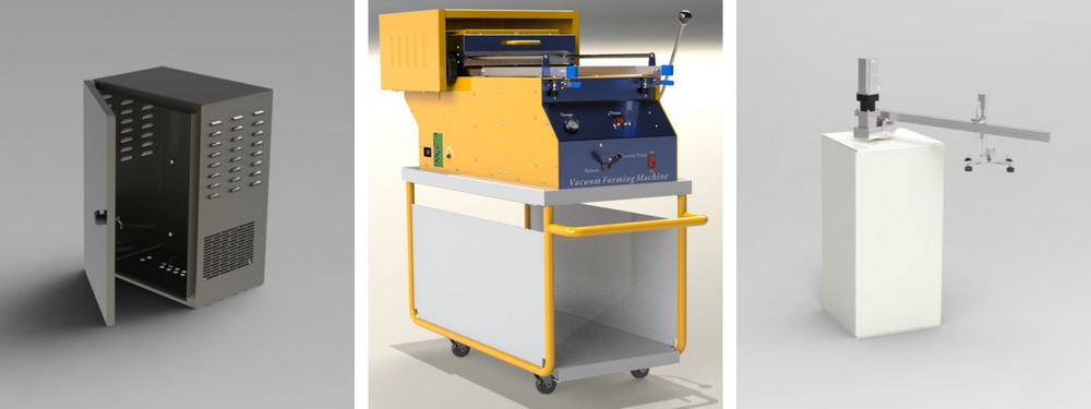
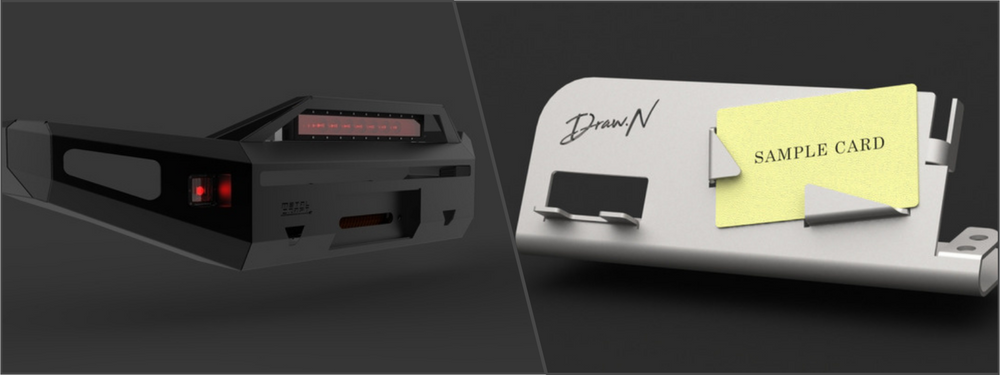
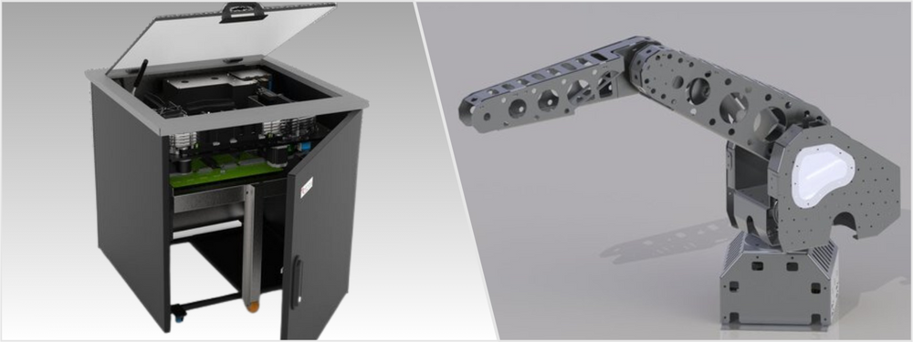
The term sheet metal refers to any metal material formed into flat pieces, a process commonly known as sheet metal design. Thickness varies significantly between materials. For example, 28-gauge stainless steel is possibly formed into a 0.015-inch sheet, whereas a 36-gauge copper can be 0.010-inch thin. Generally, any metal piece thicker than 0.250 inches is considered a plate. Extremely thin sheet metals are sometimes called leaf or foil.
Sheet metals are used for various applications such as signage, automotive, greenhouse, cookware, aerospace, decoration, artwork, and pipeline. Regardless of the purpose, they are designed to be stable, light, and elastic to some degree. Due to the demanding characteristics, custom sheet metal design is a mistake-prone undertaking, but there are methods to reduce the risk.
 Table of Contents
Optimizing Sheet Metal Design
One method incorporates direct metal laser sintering services (DMLS) into the design and production process. DMLS is an advanced additive manufacturing technology that directly creates complex and precise metal parts from 3D CAD data. This technology uses a high-powered laser to selectively fuse layers of metal powder into the desired shape.
DMLS, paired with rapid prototyping services, offers notable advantages for sheet metal design. It enables quick prototyping of complex geometries, expediting design validation and refinement. Additionally, DMLS can produce parts with intricate internal structures, enhancing stability and lightness. Overall, DMLS and rapid prototyping services improve design efficiency and effectiveness.
Designers can use SLS (selective laser sintering) technology to create plastic prototypes of sheet metal parts or assemblies. These plastic prototypes allow designers to evaluate the design’s form, fit, and function before committing to the actual sheet metal fabrication. This process can help identify and address potential design issues early in development, saving time and resources.
By integrating DMLS and selective laser sintering services into the custom sheet metal design process, designers and engineers can achieve higher precision, optimize material usage, and improve overall product performance, ultimately reducing the risk of errors and enhancing the end product’s functionality. DMLS exemplifies the importance of carefully considering design and manufacturing technologies to achieve the best possible results.
As we delve into the topic of sheet metal design, let’s explore some essential tips and best practices that designers and engineers should keep in mind when creating sheet metal drawings and designs:

RELATED: 5 Benefits of Using Sheet Metal for Your CAD Design
Sheet metal design and drawing tips
Like most modern products, sheet metal designs start as CAD drawings. Think of the designs created on a computer as the perfect final product version; however, there can be variations between the file and the manufactured object. To minimize such variations, applying the DFM (Design for Manufacturability) principle is recommended.
Every design must be created with the manufacturing process in mind, and it should be easy to fabricate using the available equipment and cost-efficient. Engaging DFM design services and consulting design for manufacturability (DFM) experts can help achieve this goal. In the case of sheet metals, the following tips should help minimize the chances of errors.
Design clarification
Overall dimension and specifications are the first things to clarify. Make sure the clarification process covers these details:
- Tolerances
- Surface flatness
- Material thickness
- Radius of corners
- Height, width, and length
- Holes (locations and diameters)
The design brief should be as clear as you can make. Mistakes can still happen, but a thorough clarification before production dramatically reduces the risk.
RELATED: How Much Do Engineering Design Services Cost for Company Design R&D?
Design simplification
CAD drawing services experts play an instrumental role in refining and altering CAD images efficiently. As many revisions as necessary can be made to remove redundant or non-essential elements, simplifying fabrication. The primary goal of design simplification is to streamline the manufacturing process while adhering to the original specifications.
Run another model analysis; you may find overworked elements during the review. As a general guideline, all the unnecessary details that don’t add value to the product are omissible. Remember, the sheet metal should still maintain its intended function after simplification. Regardless of where the simplification leads, the pre-determined specification comes first.
Decide the finish
Sheet metals come in various finishes but are either aesthetic enhancement or a protective layer. You must decide on the type of finish early on in the design phase.
- Protection: galvanized or anodized metals already come with a protective layer. If you must use bare metals, chemical conversion treatment or zinc coat can protect the sheet surface and maintain the structural properties.
- Aesthetic: powder coating – a common aesthetic finish technique – also protects to a small extent. It is not as powerful and long-lasting as a zinc coat. Another standard aesthetic finish is silk screening, typically used for stamping a text or image. Chromate conversion finish makes the sheet metal conductive – an ideal option to paint the product.
Considering various finishes and their applications, galvanized steel is an ideal choice for sheet metal design due to its durability, strength, and resistance to oxidation. However, it has limitations, as welding can release toxins. As an alternative, many companies opt for stainless steel sheet metal and apply a zinc coating post-welding. CNC programming services are crucial in streamlining the sheet metal design and fabrication process, ensuring accuracy and efficiency.
RELATED: CNC Programming Costs & CNC Machining Service Rates for Companies
Fewer tight tolerances
Near-zero tolerance is great in theory, and it offers excellent detail and snug fitting and brings the impression of a well-crafted design. Tight tolerances are often unnecessary from the perspective of practicality, and such design serves little purpose beyond aesthetics.
For the manufacturer, tight tolerance means a requirement for precision equipment and advanced fabrication techniques. While it is not a problem for the most part, the process requires more money, and higher production cost means an expensive end product. Only use tight tolerances when the product needs them for functionality, and you can rectify the unnecessary elements during design simplification.
Design drawing
A sample model or prototype is an excellent reference point for the metal fabricator. That said, fine details like specifications, materials, and machining requirements must be provided along with the design brief. An annotated design drawing serves as the ultimate guideline for the fabrication process. Detailed specifications and all related information are essential to ensure accurate manufacturing. A sample alone is far from sufficient.
Mind the holes
If there are holes, make sure each has a diameter larger than the thickness of the sheet metal. At the very least, the diameter should be equal to the thickness. Other important rules to note:
- The distance between the nearest two holes should be at least double the thickness of sheet metal. The ideal distance is six times the thickness. It prevents the holes’ deformation and maintains the material’s structural strength.
- Holes should be reasonably far away from the outer edge of the sheet. The distance between any punched hole and the edge is, at a minimum, equal to the thickness.
- The distance between a bend and a hole should be at least 1.5 times the sheet’s thickness.
The design tips help prevent tool breaking during fabrication and deformation of the sheet metal itself. Consistent hole size can also speed up production thanks to minimum tooling changes.
RELATED: How Much Do Sheet Metal Design Services Cost & What Are Prices for Freelance Design Engineers?

Mistakes to Avoid
To provide freelance metal design and fabrication services, sheet metal designers adhere to basic guidelines. However, some fabricators still face recurring errors in design or CAD models, leading to confusion during the manufacturing process.
Unspecified bends
One of the most fundamental problems is that designers draw a CAD file of a product or component as part of a solid object. The fabricators must know which parts must be formed or cut and where the bends should go. Another common issue is an unspecified thickness in the model. Sheet metal is made of a single block material, meaning the sheet has the same thickness across the board.
The minimum distance between features and the bend line
Placing tabs and holes too close to the bend lines creates a problem, and the fabrication process can punch the holes in the specification, risking sheet deformation. The ideal distance between a bend line and any feature is four times (you can probably get away with 1.5 times) the sheet’s thickness.
Perpendicular corners
While perfectly perpendicular lines or corners look pretty on a CAD file, the press brake in sheet metal fabrication cannot possibly form a 90-degree angle. Using the same bend radius (half the length of the bent area) might not be aesthetically pleasing for some designers, but it saves money on production.
RELATED: How Much do Manufacturing Services Cost for Your Company Prototypes, Products & New Parts?
Wrong material for the intended applications
Effective communication with a fabricator is essential for your company’s success, as they can advise on suitable materials for specific applications. Sheet metal design and drawing services contribute significantly to these discussions. For instance, an experienced fabricator understands that unfinished stainless steel will corrode when submerged in salt water for extended periods, a trait many metals share.
The fabricator’s expertise provides invaluable insights into various metals’ mechanical properties and optimal uses. Understanding materials’ characteristics can help prevent issues and customer complaints, ensuring a smooth design and production process. By incorporating their knowledge into the sheet metal design and drawing services, you can optimize your project outcomes and maximize efficiency.
Disregard the U-channel properties
Just because a design looks rigid on a computer screen, it does not always mean it will perform as expected in real-world applications—case in point: U-channel in sheet metal. A narrow U-channel is structurally weaker than a wide one. Generally, a 1:2 height-to-width ratio is reasonable, and a riveted or welded assembly is preferable if the channel is even narrower.
Impossible welding
Welds on the inner side of metal parts are an impressive design element for aesthetics and functionality. The only problem is that, in most cases, such a welding requirement is impossible. There is no way a welding torch can access an inside seam through a tiny opening, let alone a closed assembly. Another typical mistake is that the selected material – or its thickness – cannot withstand the temperature required for welding.
Metal melts if exposed to high temperatures, which is how welding works. When the material is too thin, it can and will deform. A minimum thickness of 0.040 inches is recommended when the assembly requires the fabricator to weld some parts.

RELATED: 5 Reasons to Hire a CAD Design Specialist to Bring Your Company’s Concept to Market
Communicate with the fabricator
One effective way to streamline design and enhance manufacturing efficiency is to establish open communication with the fabricator. Fabrication drawing services bring invaluable expertise to the table, as professionals in this field deeply understand the manufacturing process and can visualize the final appearance of your sheet metal product.
Seek the fabrication design professional’s input on efficient design and how each design element may impact functionality. While you retain the final decision-making authority, consider the fabricator’s recommendations a valuable guide to creating better designs at reduced costs. Even minor adjustments can significantly improve the manufacturing process and contribute to an optimized end product when informed by the fabricator’s expertise.
How Cad Crowd can assist
Take your sheet metal design and manufacturing to the next level with Cad Crowd’s expert services. Our global network of experienced professionals is ready to provide you with insightful tips and best practices for sheet metal design and drawing. Whether you’re looking to optimize material usage, improve precision, or streamline production, our specialists have the expertise to guide you every step of the way.
Don’t miss out on the opportunity to enhance your company’s sheet metal design process—reach out to Cad Crowd today and request a free quote.
