This post covers CAM engineering costs, company fees, and consulting service rates. The main objective of computer-aided manufacturing services (CAM) is to create a product following the parameters set during the computer-aided design (CAD) process in the most efficient way possible, to improve output and reduce waste. Combining modern machinery and computer software enables manufacturers to create precise parts and produce high-quality products. CAM software converts product “blueprints” into a code or language that a machining tool can read and understand. The code is a set of commands that drives how the machine should operate.
 Table of Contents
Cost for CAM engineering
In the United States, a CAM engineer’s hourly rate ranges from $36 to $54 per hour (around $75,400 to $111,800 annually). The average hourly rate is $44 ($90,000 per year). The initial setup cost for CAM systems and machinery is costly. For example, a high-quality vertical milling machine sells at around $50,000—and that is just one machine. An entire shop floor of CAM machinery may require an investment of hundreds of thousands of dollars. It also costs money to run the system. The hourly rate of a freelance CAM engineer needs to be high enough to compensate for the operational costs (overhead), labor, and profit margin.

CAM system components
A complete CAM system requires at least three components, including:
- Software, which generates the proper toolpaths to build the desired product
- Machinery to turn raw materials into a product as intended
- Post-processing to convert the toolpaths into commands the machine can execute
Although a CAM model system is partially a form of automation, it takes a capable CAM machinist to write a proper set of codes for efficiency and quality. The code is a series of instructions that govern the machine’s operations, such as feed rate, movement, cutting tool, coolant, and rotational speed. The machinist must manually input the codes as the product design gets more complex because complete automation is less likely to yield intricate details.
RELATED: What Is CAM? Past, present, and future
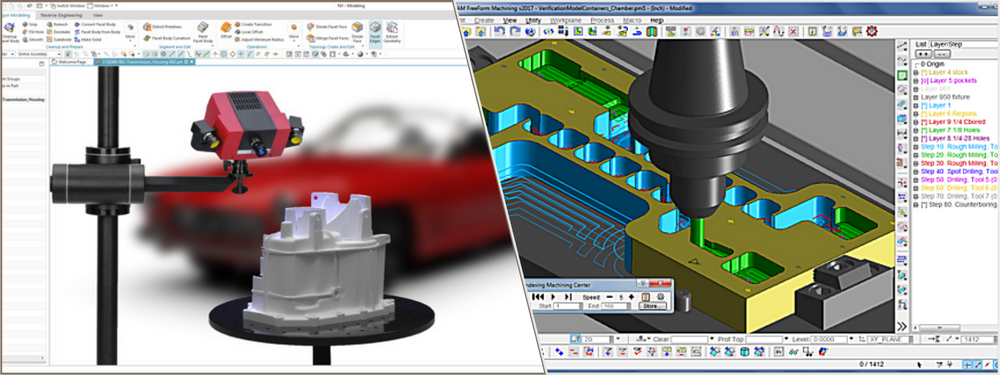
From CAD to CAM
CAD and CAM refer to different processes but are all parts of the modern manufacturing method. The CAD model focuses on design, while CAM emphasizes manufacturing. The former creates the blueprint of a product, whereas the latter takes the blueprint and generates toolpaths based on it. The product engineering process begins with CAD company services. Some engineers utilize pencil drawing during the earliest phase (ideation) and then move to CAD once the concept is ready for development.
They make a 2D or 3D model of the product, whether a simple mechanical toy or a complex aerospace part, complete with relevant information such as dimensions and materials. The model and its data are loaded (or exported) to CAM. Preparation for the “machining” of the product starts here. Machining refers to the controlled process of transforming raw materials into the desired shape; it may involve using multiple tools like lasers and drills.
CAM software needs to complete several steps before the machine comes into action:
- Create a set of coordinates for the machine to follow
- Check for any geometry errors
- Determine the machine’s required parameters, including voltage, speed, depth of cut, etc.
- Configure the best positioning for the raw material to optimize efficiency
A machinist translates all the instructions and information generated by CAM software into code language. Automatic translation is the quickest way to do it and should work well for simple designs, but manual inputs are still necessary when creating complex shapes and cuts.
RELATED: What is the difference between CAD and CAM? – History of the industry
Manufacturing automation with CAM
CAM revolves around the idea of subtractive manufacturing by a Computer Numerical Control (CNC) machine. Subtractive manufacturing creates a product by removing unused portions from the raw material, known as the workpiece. The removal is done through drilling, cutting, or grinding. Depending on the product type, designers can use a variety of workpieces such as blocks (also rods and bars) of metal, wood, plastic, and foam. With the codes ready, a CNC machine can operate an automatic run.
Some of the most common CNC processes are as follows:
- Milling: in any manufacturing application in which the removal of excess materials from a workpiece block is required, CNC milling is one of the most effective methods to get the job done. The milling process allows the workpiece to move on the X and Y axes, while the spindle (cutting tool) only impacts the Z axis.
- Turning/lathe: as the name suggests, a CNC machine of this type turns or rotates the workpiece against the cutting tool. The process can create precise cuts to cylindrical workpieces thanks to the rotational motion along the X-axis. It is effective for knurling, facing, chamfering, and carving threads. A skillful machinist can even create a hexagonal shape using a lathe.
- Plasma cutting: effective for workpieces made of conductive materials, CNC plasma is an overpowered tool that cuts through and carves thick metals with impeccable accuracy. The same is also true for water jets and laser machines.
- Routers: CNC routers are similar to milling in many respects, and both use a similar method to remove materials from workpieces. The most significant difference is that the router features a stationary workpiece table. The spindle moves on the X, Y, and Z axes. Since the spindle—the tool that experiences the most force—is mounted on three axes, it might not be rigid enough to handle hard workpieces. A CNC router is best for softer workpieces like wood and plastic.
- Electrical discharge: the most impressive feature of electrical discharge machining is that it can remove minuscule material from the workpiece to create near-zero tolerances. Think of it as a bandsaw, but instead of using a physical blade, the machine cuts a workpiece by propagating electric sparks.
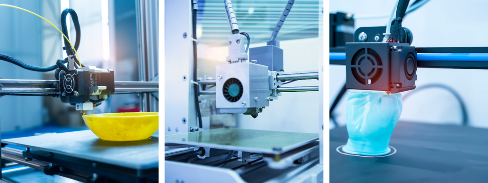
Although firm CAM services are most commonly associated with subtractive manufacturing, it is an umbrella term that covers all computer-controlled manufacturing processes, including additive methods such as 3D printing. If the code in subtractive manufacturing instructs the spindle in CNC machines, a similar code controls how the nozzle moves and extrudes filament in 3D printers.
RELATED: How 3D CAD & CAM have changed new product design

Better control
The main advantage of CAM is increased control over the product creation process. The toolpaths generated by CAM software give a straightforward overview of how a part or product is manufactured from start to end. A machinist can program a CNC process to create the exact product multiple times without compromising accuracy. If a modification is necessary, the machinist only alters a few lines of code rather than reprogramming the machine.
The initial setup cost is costly, but you don’t have to purchase the entire system to manufacture something. Instead, you can hire a freelance CAM programming engineer or consulting firm to machine the product.
Elevate your next CAM engineering project with freelance experts on Cad Crowd! 🚀
Are you ready to bring your innovative ideas to life with expert industrial design services? Look no further! Cad Crowd is your one-stop destination for top-quality, freelance industrial design services. Our global network of talented and experienced professionals is dedicated to helping you create the products of the future. Contact us for a free quote for expert assistance from our pre-vetted professionals.
Here’s why you should choose Cad Crowd for your industrial design needs:
🌟 Expertise across industries: Whether you’re developing cutting-edge electronics, efficient transportation solutions, or sustainable packaging, our industrial designers have experience across various sectors, ensuring your project receives the specialized attention it deserves.
