

Drawings are one of the most essential tools associated with Product Lifecycle Management (PLM). From the moment an idea for a product is conceived until it has been produced, the ability to visualize that product and to track all of its specifications and measurements is vital to the success of the endeavor. It doesn’t matter whether the product is a hex bolt or a house, everyone involved in the PLM process is expecting that there will be concise and accurate drawings available for review.
Of the many types of drawings (described briefly below), it is often the assembly drawing that project personnel refer to the most. And the freelance experts at Cad Crowd have the experience needed to create these assembly drawings for you.
The terminology surrounding this subject can be confusing at first. On your journey here to Cad Crowd, you have probably run across terms like assembly drawings, blueprints, detail drawings, engineering drawings, shop drawings, technical drawings, and working drawings. While each has its own definition, you’ll find that even professionals tend to use many of these terms interchangeably. Let’s try to sort this all out.
In general, drawings of this type are graphical representations that provide the specifications needed to accurately produce (manufacture, build) the product in question. As mentioned above, the product can be just about anything from a piece of hardware to be manufactured to a construction project that needs to be built.
Although you are certain to find disagreement, all four of the following terms can be used interchangeably:

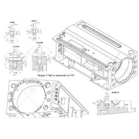
In the past, the term blueprint referred to any of the drawings listed above that were reproduced using a specialized photochemical process. White areas of the drawing would be reproduced as blue, and anything in black (usually lines, numbers, and lettering) would be duplicated in white. Think of it as a sort of negative image of the original. Nowadays, the term is quite often used as a synonym for any type of drawing in our list, regardless of color. For example, either of the two pictures shown here is often referred to as a blueprint:
Any of the types of drawings listed above can be broken down into two categories: detail drawings and assembly drawings:
Although some people will use the term detail drawing as a synonym for any of the other types of drawings listed above, a detail drawing will usually involve only one part (or type of part) and will contain a more significant amount of information about that part. As such, there are two types of detail drawings:
The majority of products sold around the world are built out of a number of components. At the lower end of that scale are items like the hex bolt mentioned earlier and plastic toy dinosaurs that consist of just one part. At the upper end of that scale is the Space Shuttle, which is composed of about two-and-a-half million parts. That’s where assembly drawings come in.
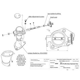
An assembly drawing is a drawing of an entire product that shows how all of that product’s individual components fit together. In its strictest interpretation, an assembly drawing shows the product in its final, assembled state, but as we’ll explain in a little bit, that isn’t always the case. An assembly drawing, at a minimum, will usually contain several elements: one or more views, a bill of materials, and a title block.
There are a number of ways to visually represent a product in an assembly drawing. In general, though, you are likely to encounter just three types of views:
Orthographic views. Imagine taking a picture of a three-dimensional object from directly above, or from in front of it, or beside it. These two-dimensional top, front, and side images are known as orthographic views or orthographic projections. (The term comes from the Greek root ortho, meaning “straight” or “right.” Anyone of the three images forms a right angle with each of the other two.)
Perspective views. The illusion that makes parallel lines (like railroad tracks) appear to converge in the distance, and that causes objects to appear smaller the farther they are away from you is called perspective. Perspective views are two-dimensional images that approximate the three-dimensional nature of objects. This type of view is used mostly in drawings of larger objects.
Isometric views. Isometric views are similar to perspective views in that they are 2D representations of 3D objects. Vertical lines appear vertical, but horizontal lines remain parallel (i.e., there are no vanishing points). 
Assembly drawings often contain an isometric view, either by itself or in combination with orthographic views. Here is an outstanding assembly drawing that contains three orthographic views and an isometric view of a spray bottle. You may have noticed that not all of the assembly drawings shown here contain dimensions. This is also not that unusual. If the measurement information would clutter up the image and make it harder to read, it’s not unusual for it to be left off the drawing. For example, the neck of a bottle has a whole series of numbers that describe the opening and the thread configuration (collectively known as the neck finish) associated with its design. To include all those numbers with the other dimensions shown in this drawing would clutter up an otherwise clean layout (although this information might be placed in the title block or bill of materials sections, to be discussed shortly).
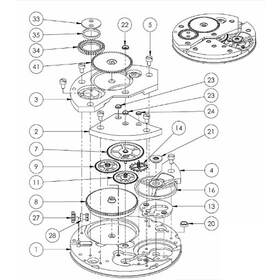
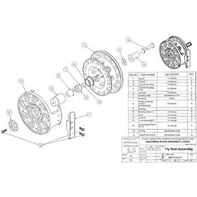
This is a good opportunity to discuss a specific type of assembly drawing known as an exploded view or exploded drawing. Instead of showing the parts of an object in their final, assembled position, these images show the components in a slightly separated fashion, but drawn in such a way that they clearly show the relationship of the parts to each other, and to the assembly as a whole.
Exploded drawings are almost always created as an isometric view. They are often used for simpler designs such as the bar-yoke assembly shown here. They can also be quite complex, like this exploded view of an exercise machine. And below is a very clean, sharp assembly drawing of a drafting table showing both an exploded view on the left, and the components in their final, assembled position on the right
Whatever type of views you need in your assembly drawings, contact us for a quote! We can put you in touch with an assembly drawing services firm that will design the perfect drawings for your project.
Yes and no. Assembly modeling is a much more intricate and complicated process involving what are known as three-dimensional solid model drawings of objects using sophisticated computer software. But the core concepts are the same as with assembly drawings, and in fact, Cad Crowd has a qualified network of freelancers who can design an assembly model for you, if that is what your project calls for. Check out our assembly modeling service page for more details.
People from all walks of life engaged in businesses of all types and sizes make use of assembly drawing services:
| Architects | Engineers |
| Component manufacturers | Entrepreneurs |
| Construction workers | Fabricators |
| Consumer-goods manufacturers | Inventors |
| Consumers | Parts suppliers |
| Contractors | Prototype builders |
| Designers | Quality-control personnel |
Cad Crowd has the resources to help you achieve your project goals through the use of assembly drawing services. Professionally created, high-quality drawings will reduce both the time it takes and the money you spend to get your new products to market.
We can help you find the assembly drawing services company or freelancer to help you stand above your competition. Regardless of the complexity of your assembly drawings, Cad Crowd has the professional resources to help you manage your projects. Contact us today for a free quote.
Our freelance assembly drawing designers are among the most talented in the industry. Cad Crowd has an extensive network of pre-qualified and vetted freelancers available who can develop assembly drawings that will help you complete your project on time and under budget. Contact us to obtain a free, no-obligation quote today!


